Improved Transition Adds to Capacity of Flume
Improved Transition Adds Capacity To Flume Change in Hydraulic Characteristics Increases Flow Limit in Agua Fria Project
By J. A. FRAPS, Designing Engineer, Maricopa County Municipal Water Conservation District No. 1.
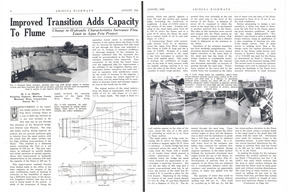
IMPROVEMENT of the transition intake section of the Agua Fria River crossing flume at a cost of $500 has effected an 11 per cent increase in the flow that can be put through this structure of the Roosevelt Irrigation District near Phoenix. The original intake section, during capacity operation, did not provide sufficient gain in velocity from the canal section, with the result that the water surface was too high, striking cross-members of the flume. This resulted in a skimming action restricting the flow to a net capacity of 300 sec. ft. The new transition, as indicated by careful studies and initial operation at partial capacity, shows that improvement in hydraulic characteristics at the entrance will raise the capacity of the flume to 400 sec. ft.
This improvement resulted directly from studies made in the office of the state engineer at the request of the state certification board of Arizona in reference to the feasibility of improving a $600,000 bond issue of the Roosevelt Irrigation District that was to be used in lining canals of the system. A study of the economics of lining the canals involved the carrying capacity of the Agua Fria River flume. The lining The typical section of the canal upstream from the flume is trapezoidal, with a bottom width of 8.6 ft., side slopes of 1.1 and a 7.2 ft. water depth. The canal is lined with Gunite, which was placed against a loose fill and has settled and warped badly, increasing the coefficient of roughness. A slope of 0.0002 exists in this section of the canal. Gradual widening of the canal takes place from 50 to 100 ft. above the flume, and at a point 50 ft. above the flume the canal has a bottom width of 10 ft. and side slopes of 1.54:1. A Lennon-type flume, with semicircular section 13.37 ft. in diameter, forms the Agua Fria River crossing. This flume is 6,000 ft. long and has a slope of 0.0006. Because of a small amount of sand carried in the canal it has been necessary to protect the flume with asphalt paint. This tends to increase the coefficient of roughness, as the heat of early summer melts the asphalt coating, causing it to run down the sides of the flume, and to accumulate in small, rough patches. Also, pressed floor rose vertically at the end of the sand trap to the level of the bottom of the flume. A distance of about 20 ft. remained in which the water in the canal had to be accelerated to produce uniform flow in the flume. The sides of this transition were curved and merged into the flume section by means of a short warped section (Fig. 1). This warped section had a distinct break in alignment at the entrance to the flume. Operation of the entrance transition has been decidedly unsatisfactory. Ob-servations showed that the curve caused higher velocities on the outer bank of the canal and that the bents of the bridge resulted in considerable turbu-lence. Below the bridge the velocity was decreased materially on account of passing through the sand trap. Turbu-lence created at the curve and by the trestle bents was increased as the water loss of water over the sides of the flume amounted to from 10 to 15 sec. ft. un-der such conditions. Before attempting to design a new transition, a study was made to deter-mine the safe flow in the flume, assum-ing good entrance conditions. In mak-ing this study, Bakhmeteff's "Hy-draulics" was found to offer a quick and simple solution, using an application of a plan consisting of drawing two rela-tively simple curves. One of these curves is nothing more than a dis-charge curve for various elevations of water in the flume, using known coef-ficients in Kutter's formula. A value of n=0.01355 was used for the flume, as determined by Fred C. Scobey, in tests made on the structure during 1929. The second curve is termed the entrance discharge curve and is obtained by com-puting the discharge in the flume from assumed differences in head between the water-surface elevation in the flume and in the canal, using a constant depth in the canal equal to the depth that will obtain with the canal full. Allowances were made for entrance losses in the transition section. A point where these two curves intersect determines the dis-charge in uniform flow, and was found to be 390 sec. ft., with a freeboard of 3½ in. in the flume. In making the design for the entrance transition the method outlined by Jul-ian Hinds ("Transitions, Am. Soc. С. Е. 1928") was used, which requires that the drop in water surface between the canal and the flume must be made grad-ually and without creating disturbances. The total drop in water surface is com-puted by adding 10 per cent to the velocity head loss, provided that certain assumptions relative to length of tran-sition and maximum change in direction Small nodules appear on the sides of the flume, about the size of a 25c piece and extending as much as 1½ in. from the flume surface. The canal makes an 8-deg. turn, be-ginning 150 ft. above the flume intake and strikes a tangent again 50 ft. from the entrance. A timber bridge has been constructed across the canal 60 ft. up-stream from the flume with a double row of trestle bents which present a definite obstruction to flow. Im-mediately below the bridge the canal section widened out appreciably to ac-commodate a sand-trap structure. Not only did the sides of this trap give a greater cross-sectional area but, in addition, the bottom of the canal was de-pressed 3 ft. to provide a place for the sand deposit. Beginning at the bridge, the bottom of the canal sloped sharply for 144 ft. (Fig. 2) and then flattened out for a distance of 13% ft. The de-passed through the sand trap. Upon reaching the transition proper the water surface began to drop, but the distance was so short and the turbulence so great that a full drop could not be obtained before it reached the flume. As a re-sult water level at the entrance was higher than required for uniform flow in the flume. This resulted, during capacity operation, in the water surface striking the horizontal structural steel angles across the top of the flume, re-sulting in a skimming action (Fig. 3). Development of uniform flow to the capacity of the flume was not obtained for a considerable distance below the entrance, and meantime an appreciable volume of water was spilled over the sides. The quantity of water that could be transported through the flume without spilling was 360 sec. ft. This could be crowded up to 380 sec. ft., but the(Continued on Page 24)
Already a member? Login ».